Visualizing Protein Motions with Static Images
In 2011 I worked with Canan Atılgan and Ali Rana Atılgan on the figures of their paper “Network-based Models as Tools Hinting at Non-evident Protein Functionality” in Annual Review of Biophysics, Vol. 41. There, I once again faced the challenge of showing protein dynamics in static images; since scientists usually publish in static (printed) media, showing these motions in figures is a common problem because proteins are extremely complex structures and even drawing them without motion is a nightmare.
I had had some previous experience with this problem in Image of Science 2010 in Ayşe Özlem Aykut’s project, and then in the Structural Biology class I took in Sabancı University. The method I saw being used was putting in lots of red arrows/cones (one for each residue), and I wasn’t happy with how they looked; ugly, busy, and uninformative.
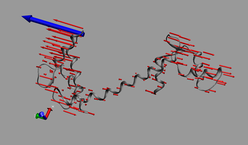
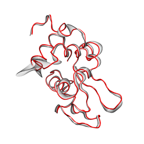
This time Canan and I worked out a method (within the software VMD – Visual Molecular Dynamics) that we thought was more successful (and good-looking) than the arrows in showing which parts move to what degree and in which direction. Below is a snapshot from a figure in that paper; at the bottom you can see the motion visualization that we created.
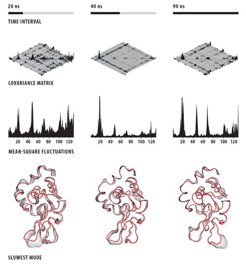
I want to share this method with the world in detail for people who might want to use it. Below are our notes explaining the process in VMD.
The Method
The initial file should have the average structure data as well as the mode vector added onto the average structure coordinates in pieces. These data should be written into a single pdb trajectory file, which is then read into VMD. (The first 20 frames out of a total of 100 seems to work fine for our system.)
Step 1 – MenuGraphicsRepresentations, make the Drawing Method “Tube” and Radius “0.1”.
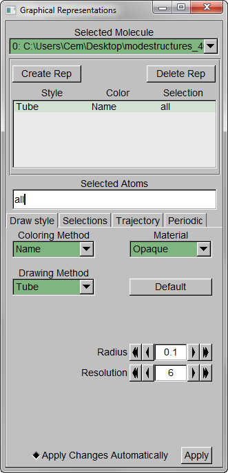
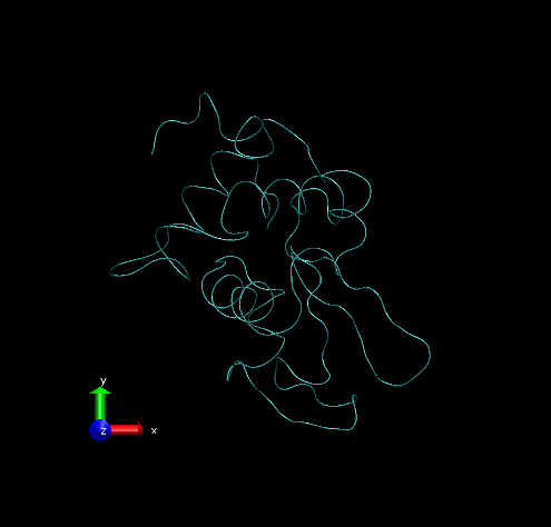
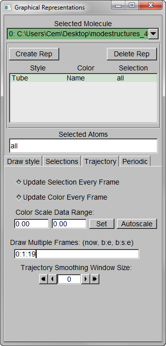
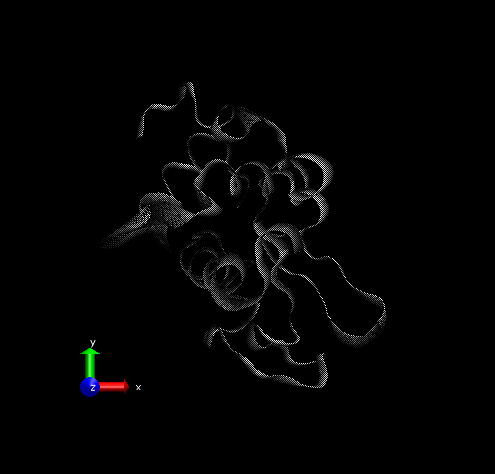
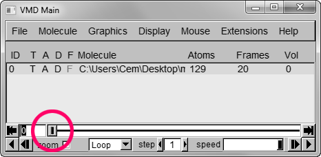
Step 2 – Show all trajectory snapshots at once. This is achieved under the Trajectory tab, Draw Multiple Frames option, using the frame values “0:1:19” (since we have 20 frames).
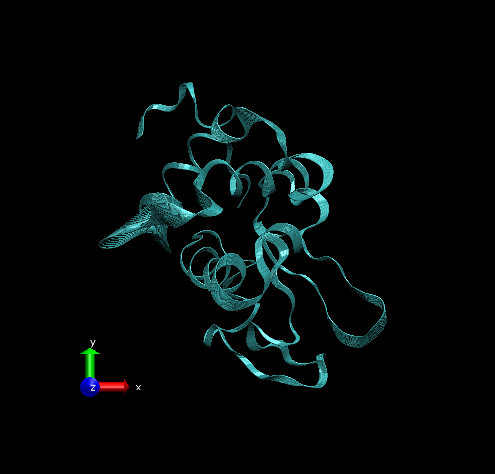
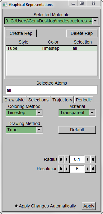
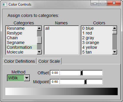
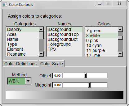
Step 3 – Make the Coloring Method “Timestep” (under “Trajectory”), also set the Material “Transparent”. Default coloring is red to blue. You can change this from MenuGraphicsColors, Categories box “Conformation” selection. We preferred white to black (“WBlk”, with offset “0.0”, midpoint “0.6”) because we wanted to show more clearly where the movement ends (on a white background).
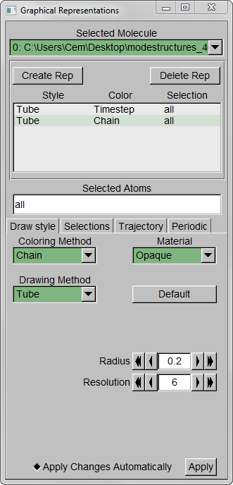
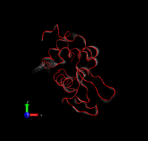
Step 4 – Make a copy of the representation (from Create Rep under Graphical Representations), this time displaying the initial structure only. (We wanted to show the initial structure with red; you may want to emphasize a different state. Be sure to select the frame of your choice in the main screen). Select “Tube” with Radius “0.2”; color it by a different Coloring Method and choose an opaque Material.
Step 5 – Set background color to white from MenuGraphicsColors, “Display” Category, “Background”.
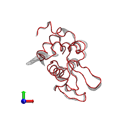
For rendering, we preferred the Tachyon module, which generates files that can be opened in Photoshop. Below is the result, with some Brightness increase in Photoshop.
Addendum
I’m very happy to learn that Zeynep Kürkçüoğlu Soner, a scientist working on generating atomistic conformers for proteins with various size, saw this tutorial and adapted it for her purposes on PyMOL. Here is her method with her own words:
It is generally hard to visualize protein motions on static images, contrary to movies playing sequentially the snaphots obtained from simulations such as molecular dynamics. For my thesis and the paper that is related with it, I was trying to find a means to clearly present such motions, and as Cem mentions in his tutorial, the vectors are not always the best way. Then, I encountered Cem’s work related with “visualizing protein motions with static images” and realized that the representation that I have been looking for was right in front of me! In my work, I do not have a specific direction vector as in the case of normal vectors, however I thought that with a little modification, the method can be suitable for my figures as well. Voilà, the result for p38 kinase:
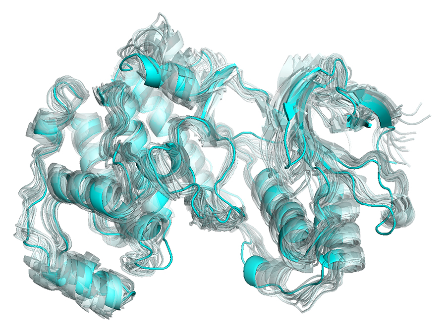
The figure is obtained from the software PyMOL, as many structural and computational biologists are familiar with (like VMD). Personally, I like the colors and shapes obtained from PyMOL more than the ones from VMD.
The procedure is quite simple:
- Load the frames from MD to PyMOL as separate objects (I had 18 frames, but for a relatively small protein with 320 residues, 100 frames can also work).
- Show all as cartoon by typing on the command window:
show_as cartoon, all
- Set cartoon transparency from “off” to 0.6:
set cartoon_transparency, 0.6
- Set cartoon transparency “off” for the starting structure (or the average structure, basically which structure you want to stress). Let’s say the name of this object is “obj_start”:
set cartoon_transparency, off, obj_start
- Set background color to white:
set bg_rgb, white
- Color all frames with the color that you prefer. In this example, I preferred cyan for the starting structure, and palecyan for the others:
color palecyan, all
color cyan, obj_start
- Optional: For rendering, you can use “ray” command, but generally it takes too much time. I simply take the printscreen and edit the resolution in Photoshop.


Hello!
I really really love these images that you have up here and have followed this tutorial. Thank you so much.
You appear to be an expert with VMD and so I do have a technical question to ask about the cylinders and Tcl scripts.
I downloaded the VMD program and was wondering how you make cylinders which can trace the contours of your polymer or protein.
e.g. For instance imagine that my protein below is:
C4
|
C1 — C2 — C3 | C5 — C6 — C7
The cylinders would span C1-C3, then C3-C4, C4-C5 and finally C5-C7. Do you have any advice??
Best Wishes,
Alaina
Thank you Alaina, I’m really happy that you found this useful. However, I’m not an expert on VMD and I don’t have an answer to your question, I’m sorry.